BLTouch doesn’t fix it all
So you got a BLTouch or some 3DTouch working, and you’re wondering why things aren’t printing like they should. It was supposed to automatically compensate any bed irregularities, wasn’t it?
Chances are you did nothing wrong, but your printer is. Don’t worry, you can fix it, or just work around it.
How BLTouch works
Automated bed leveling correction works by finding the difference between two data points:
- Z axis home position
- Z height that triggers the probe
By probing the Z height of several points around the bed, it’s possible to calculate a rough estimate of its shape, and compensate for it during printing.
Material
- Ender 3 v2
- Board v4.2.2 with silent drivers
- Ender 3 V2 3DTouch/BLTouch Mount (with wire duct), on Thingiverse
- Makerbase 3DTouch (more on GitHub)
- Jyers Marlin Firmware
- v1.2.1 (E3V2-UBL-BLTouch-10x10-v4.2.2)
Optional:
- OctoPrint (in Docker)
- plugin: Bed Visualizer
- Marlin GCODE
Also used:
- Extra thermal insulation
- PC+fiberglass bed
- Magnetic rubber bed
Repeatability
The key to a good bed leveling, is repeatability, or how to get the same measurement for the same thing every time, over and over, hundreds of times, thousands of times. Every time the probe touches the bed in the same spot, the firmware needs to think it’s at the same Z height, and it needs to match the same nozzle Z position. Otherwise, you’re getting Z axis creep.
Note that measures don’t need to be reproducible, your bed and sensor can be as misaligned as you like, it just needs to give the same value every time.
Check for Z axis creep
The simplest check is:
home Z
for 1 to 100
 probe point
if last point != 0 then
 alert("Z axis creep!")
In Marling GCODE, that would be:
G28 ; home X Y Z
G29 P0 ; zero mesh data
; for 1 to 100
G29 I1 ; invalidate closest point to the nozzle
G29 P1 C ; probe invalidated point
; end for
G29 T ; output topology
You should expect a repeatability error of:
- BLTouch: 0.005~0.015 mm
- 3DTouch: 0.010~0.050 mm
(BLtouch VS 3Dtouch 3D Printer bed leveling sensor match up, on YouTube)
Desired error level for a 0.20 mm nozzle:
- <0.01 mm - perfect
- 0.01~0.05 mm - good enough
- 0.05~0.10 mm - some adhesion errors
- >0.10 mm - bad
- >0.50 mm - worse than no correction at all
Examples of Z axis creep
 (Automatic bed leveling through LCD)
After homing Z, probing started at the lower left corner, then kept going up and in diagonals to the lower right. Maximum height measured at top right corner.
(G29 P1 bed leveling)
After homing Z in the middle of the bed, probing started in kind of a spiral. Maximum height at the outside of the bed.
 (Left-to-Right probing)
Custom “left to right” probe in an S pattern: probe 10x10 left to right.
 (Right-to-Left probing)
Custom “right to left” probe in an S pattern: probe 10x10 right to left.
Averaging it out
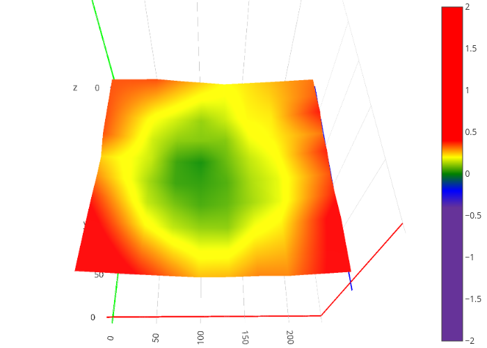
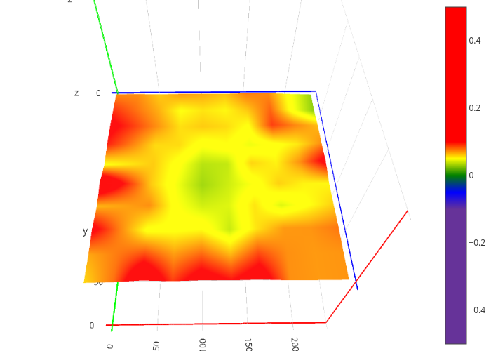 (Maximum error at each point after leveling 4 times)
After repeating the same “center to outside” measurement 4 times in a row, calculated an average, then extracted maximum distance from average for every point.
Points probed last, show the largest variability. Which means that averaging the measurements won’t be enough.
Why it happens
Every point probe actually consists of several moves:
- Move XY to probe position
- Move Z down until probe touches
- Move Z up
- Move Z down again, this time slower
- Move Z up
That is 4 times that any inaccuracy in the Z axis can introduce an error. For 8x8 = 64 points, that’s 256 moves, which even with 0.001 mm Z axis creep per point, means a 0.256 mm error for the last point, which skews all the measurements.
Effectively, you need less than 0.0001 mm average error per Z move to achieve 0.025 mm precision over 256 moves.
Fixing it
In an ideal world, every time the firmware requests a Z height of 0, the print head should go to the same place.
This means the following need to be calibrated:
- Bed height due to temperature
- Stronger springs can help reduce variability
- Nozzle height due to temperature
- Can’t fix this, correct by adjusting the Z Offset
- Print head wobble
- Eccentric nuts, need to be just tight enough to press into the gantry but not to rotate freely
- X gantry sagging
- Eccentric nuts, adjust both left and right sides so all the wheels apply a similar pressure
- Z axis leadscrew
- Reduce backlash with an anti-backlash nut
- Make sure it sits firmly in its part of the motor coupler
- Z axis stepper motor driver VREF
- Skipping steps will cause Z axis creep
In practice, there is just so far these can be taken without increasing costs and rebuilding the whole printer, so we need the next best thing: deal with it.
Brute force, or “Center-to-Center”
Since we can’t fully trust the calibration, or the averaging of measurements, let’s go back to the basics:
- Bed leveling requires a height measurement as precise as possible between “home Z” and “probe point”, for every point of the correction mesh.
That can be done with:
home XY
foreach point
 home Z
 go to point
 probe point
repeat a few times for good measure
take an average
if there is too much measurement error
 try to fix some of the hardware
 repeat from the beginning
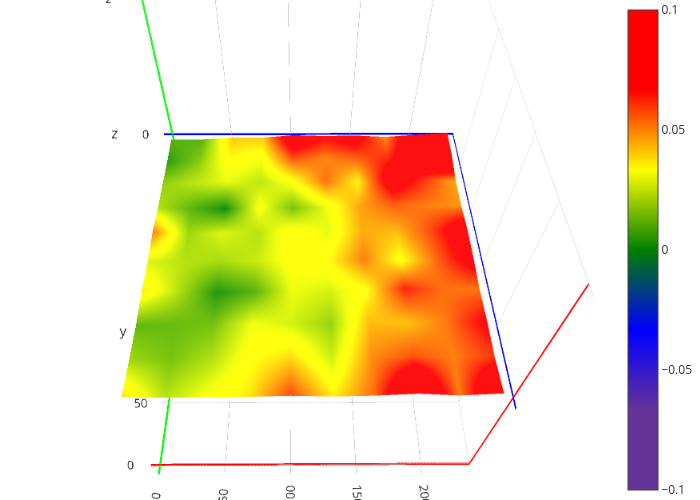
Custom “center to center” probe, pattern irrelevant:
This takes a while, but each point is probed relative to whatever G28 Z thinks zero means. Since it does the Z homing at the same spot (center of the bed), the error effectively gets reset for every point, so the average ends up being under 0.02 mm.
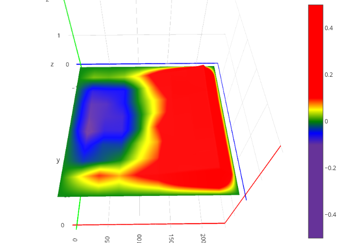
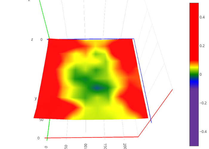 (Final correction mesh)
The final mesh looks much more realistic for a rubber magnetic bed that’s moved slightly off-center.
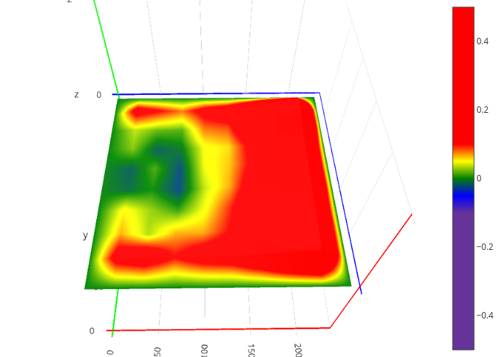
Fixing the borders
By default, the firmware’s G29 P1 doesn’t probe the outermost points. These can be filled with G29 P3, but as they say “garbage in, garbage out”, so a poor measurement will lead to an even worse mesh.
Some alternative strategies would be:
- Leave the unpopulated points at 0. Kind of dangerous, since the head can slam into the bed, but good enough if the bed is concave with the center being the lowest point.
- Fill with “highest neighbor” values. Safe bet, but will have bad bed adhesion at the borders (particularly relevant for the initial purge line).
- Fill with “lowest neighbor” values. Good enough for a rubber based magnetic bed.
Verifying the mesh
(TO BE CONTINUED)
ToDo
…so this turned out to be a somewhat longer write-up, and it’s still missing several things, but I’m tired now.
- GCODE generator for different mesh sizes and patterns
- Import/export data between Marlin, LibreOffice Calc, Google Sheets, and Plotly
- Calculate average, max, min, deviation for any mesh
- Calculate different border corrections
- Print test pattern